
Page 126 - eBook_Proceedings of the International Conference on Digital Manufacturing V2
P. 126
Proceedings of the International Conference on Digital Manufacturing –
Volume 2
MECHATRONIC BLOCK DIAGRAM OF THE SYSTEM
The system's block diagram illustrates the central role of the
Arduino Nano microcontroller, which coordinates all movement
functions and operational processes, as depicted in Figure 46.
The power distribution network utilises the same 12-volt battery
that receives charge from the solar panels, routing electricity
through a buck converter and relay modules to supply system
components. The Arduino Nano receives its 5-volt operating
power from the buck converter configured to the appropriate
voltage level. LDR sensors mounted at the system's apex provide
continuous light intensity feedback to the microcontroller. Based
on detected light variations, the Arduino calculates and executes
positional adjustments to align the solar assembly with the sun's
current location.
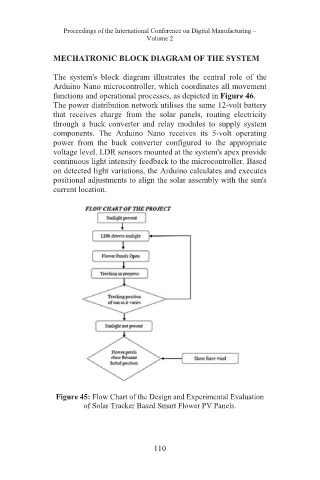
Figure 45: Flow Chart of the Design and Experimental Evaluation
of Solar Tracker Based Smart Flower PV Panels.
110